E46 328i The Mystique Blue Thunder...
- Thread starter Fireuz
- Start date
-
Click here to become an Official Member of BMW Club Malaysia Download Form
You are using an out of date browser. It may not display this or other websites correctly.
You should upgrade or use an alternative browser.
You should upgrade or use an alternative browser.
SilverBullet
Club Guest
- Joined
- Feb 27, 2008
- Messages
- 1,538
- Points
- 0
wah wah wah...congratsss bro!! finally the Blue Beast is revealed!! very nice indeed...slurrrppsss
love the colour..a little bit de-clingonsss...muehehehehe
love the colour..a little bit de-clingonsss...muehehehehe
Fireuz
Club Guest
- Joined
- Dec 9, 2008
- Messages
- 754
- Points
- 18
SilverBullet;647643 said:wah wah wah...congratsss bro!! finally the Blue Beast is revealed!! very nice indeed...slurrrppsss
love the colour..a little bit de-clingonsss...muehehehehe
Thanks to you as Tuan Penasihat 25% as well due to the ideas contribution. Eventhough 25%, but it's enuf to remove the "clingonss" identity in this ride.
SilverBullet
Club Guest
- Joined
- Feb 27, 2008
- Messages
- 1,538
- Points
- 0
show me more pics of the ass bro! dgn position lobang dia skali..i want to ponder where to put your quad-lobang-jubo next..hehehehe
ooh btw, nice gear knob there..looks very fancy..ade set utk manual tak? hehe
ooh btw, nice gear knob there..looks very fancy..ade set utk manual tak? hehe
aidilj
Official Member
- Joined
- Jul 3, 2010
- Messages
- 2,291
- Points
- 0
Fireuz;647658 said:Next Phase of the Project:
You guys thinking what I'm thinking?? :smokin::driver:
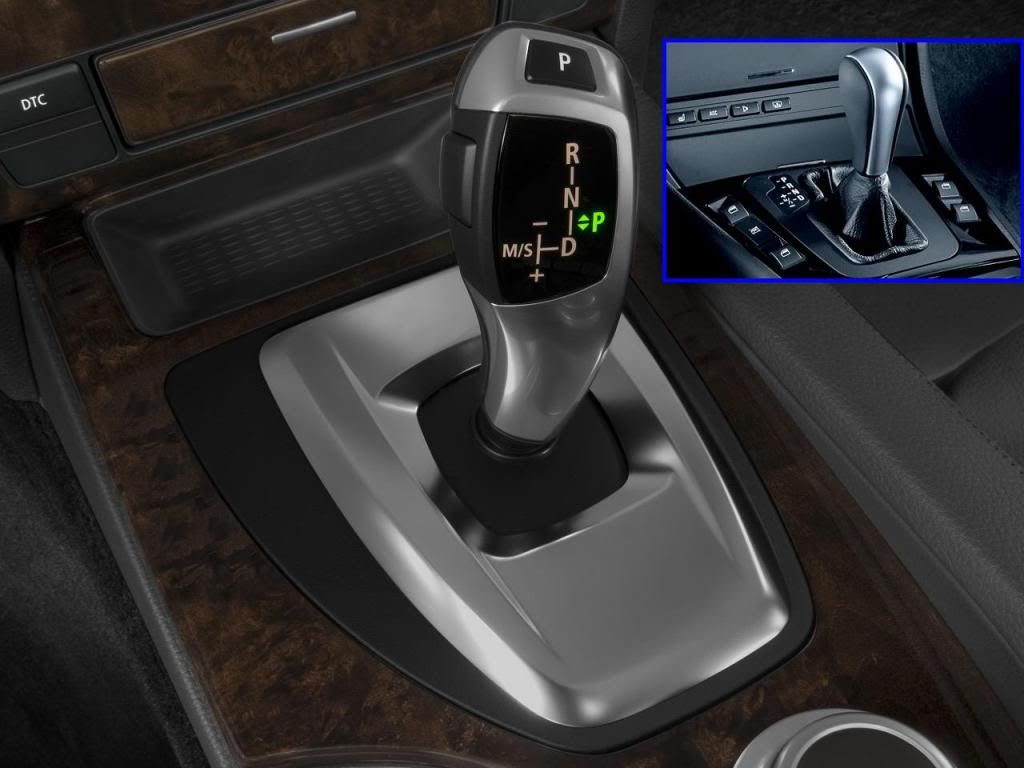
Bro Fireuz, exactly! DCT shifter in e46 has been done before, look around e46fanatics.com. just need to find the knob and everything else can be figured out..
http://www.e46fanatics.com/forum/showthread.php?t=775641
The machine is very well done bro, good job
Cheers
Fireuz
Club Guest
- Joined
- Dec 9, 2008
- Messages
- 754
- Points
- 18
SilverBullet;647684 said:show me more pics of the ass bro! dgn position lobang dia skali..i want to ponder where to put your quad-lobang-jubo next..hehehehe
ooh btw, nice gear knob there..looks very fancy..ade set utk manual tak? hehe
Please find below picture for your perusal.

What do you think if I put exhaust tip instead? cause planning to swap the bumper when time and budget permit:stupid:. Kasi sarung lobang dulu before change the ass butt:bootyshake:..
About the gear knob, I think BMW does have the illumination knob for manual, but no gear selector indicator I guess.
SilverBullet
Club Guest
- Joined
- Feb 27, 2008
- Messages
- 1,538
- Points
- 0
Fireuz;647741 said:Please find below picture for your perusal.

What do you think if I put exhaust tip instead? cause planning to swap the bumper when time and budget permit:stupid:. Kasi sarung lobang dulu before change the ass butt:bootyshake:..
About the gear knob, I think BMW does have the illumination knob for manual, but no gear selector indicator I guess.
can't really see clearly, but seems like your existing tips are slightly inward hidden under your bumper..IMO they need to be changed to bigger and longer ones bro..so that they won't look lost in your buff-ed up rear bumper..i think Hakim has two pairs of Remus tips for sale (http://www.bmwclubmalaysia.com/forums/showthread.php?41824-WTS-Remus-tip-4pcs) which may look awesome on your car..if you're thinking about going fully-functional quads, then we need to discuss it offline over a couple of cold ones >>> teh tarik ais..hehe..a few routes to choose from; fully custom quad exhaust, back-box from Taiwan, fake tips only etc.
Fireuz
Club Guest
- Joined
- Dec 9, 2008
- Messages
- 754
- Points
- 18
2011 Massive Quicksilver Transformation Project
Phase: Retrofit LCI E60 Knob into E46 Gear knob (PART 1)
Step1:
Must select the correct LCI gear lever since there've 2 type of it. One for LHD and another for RHD.
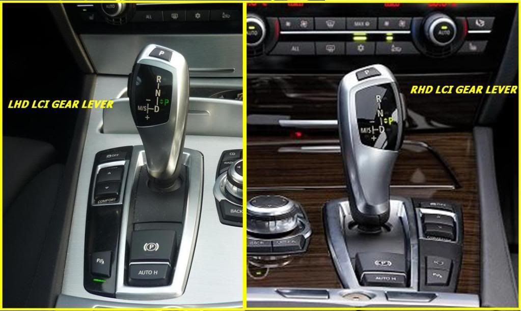
Searched over the web to buy the RHD LCI lever, very hard to find, but atlast managed to get it on ebay. Compare the price between LHD and RHD LCI gear lever, the LHD is cheaper than RHD. I would say, with used RHD LCI lever, you are able to get brand new LHD LCI gear lever. Bought it at USD280 , including expedited shipment.
P/S: Don't buy this knob at >>HERE
Phase: Retrofit LCI E60 Knob into E46 Gear knob (PART 1)
Step1:
Must select the correct LCI gear lever since there've 2 type of it. One for LHD and another for RHD.

Searched over the web to buy the RHD LCI lever, very hard to find, but atlast managed to get it on ebay. Compare the price between LHD and RHD LCI gear lever, the LHD is cheaper than RHD. I would say, with used RHD LCI lever, you are able to get brand new LHD LCI gear lever. Bought it at USD280 , including expedited shipment.
P/S: Don't buy this knob at >>HERE
Fireuz
Club Guest
- Joined
- Dec 9, 2008
- Messages
- 754
- Points
- 18
aidilj;647866 said:Good stuff, can't wait for more..
Another thing to note is that the DCT shifter doesn't have the physical/mechanical switch (the one you need to press on the lever to move out from P).
Thanks bro. As for the LCI mechanical switch to/from "P" position, it just pointless on our E46 because to move the "P", we just need to press the brake pedal+pull the stick, but not for LCI selector, because the mechanical switch is actually normal switch to activate the electromagnetic to allow the gear selection to be moved.
Below picture is taken from inside the selector.
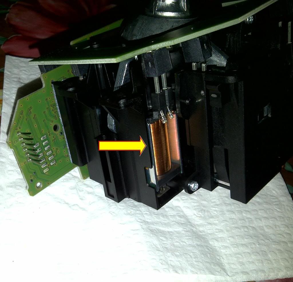
Once you press that mechanical switch, then you'll be able to move the stick from "P" to other position (it's all about switching in E60>), otherwise, the stick remain at the same position. But for E46, it's enuf for us to press the brake paddle to move the stick from "P" to other position. So, this mechanical switch also functionless in this retrofit.
Fireuz
Club Guest
- Joined
- Dec 9, 2008
- Messages
- 754
- Points
- 18
initialM;647920 said:Wow bro dasat gear ko. Panjang betul!
Haha.. Ini la dikatakan batang gear anak Melayu.. Panjang dan mantop
Mine still under-construction with LCI knob. Will update about it soon.
Fireuz
Club Guest
- Joined
- Dec 9, 2008
- Messages
- 754
- Points
- 18
2011 Massive Quicksilver Transformation Project
Phase: Retrofit LCI E60 Knob into E46 Gear knob (PART 2)
To execute this steps, you'll require:
1) 3mm wires (20cm/8pcs)
2) Multimeter
3) Soldering Iron with lid (high flux)
4) Wire cutter
5) Healthy brain :hmmmm:
Step 3:
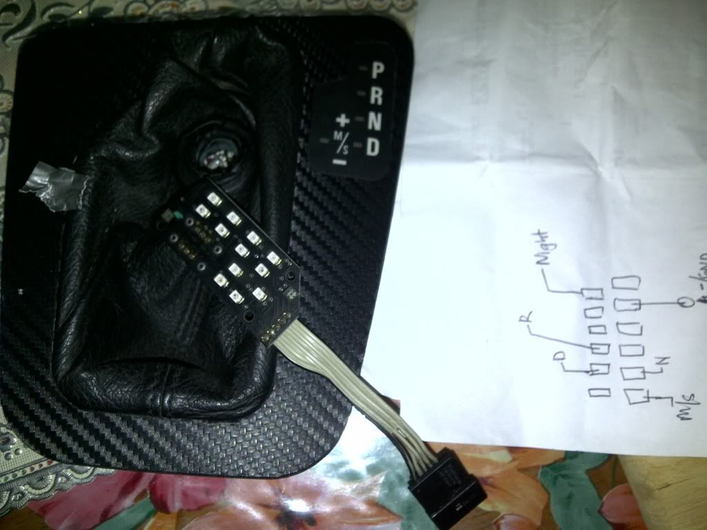
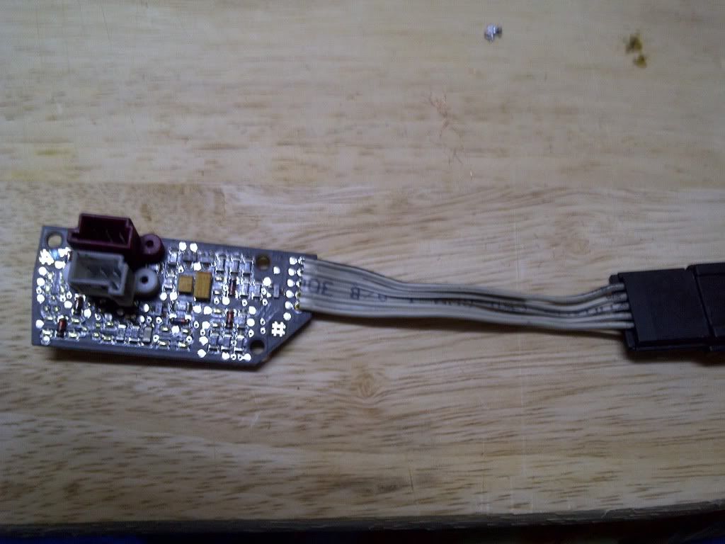
Remove the gear faceplate and take out the gear light indicator to find the right signal for the right light indicator (PRND, M/S, GND)
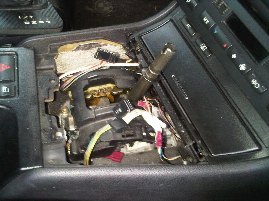
Take out the gear light indicator:
Upside view:
Downside view:
Step 4:
Upon the investigation on the original light indicator and LCI gear knob, I found that the indicator signals should goes as below wiring by tapping the extra soldered harness onto LCI lever's circuitry board.
This is my blueprint of the tapped harness:
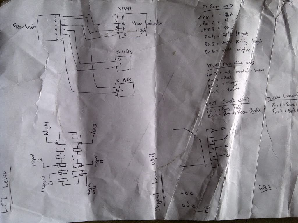
Explanation of the blueprint:
The LCI Knob wiring is as follows:
Pin1 (white wire): "R" indicator
Pin2: "N" indicator
Pin3: "D" indicator
Pin4: 0V/Ground for parking/driving light illumination } dim lighting
Pin5: +12V for for parking/driving light illumination }
Pin6: +12V for the brighter "R", "N" and "D/S" indicator
+ve signal @ "P" light: "P" indicator
X1599 is the big white connector:
Pin2: connect to the "P" +ve signal from knob
Pin3: red wire
Pin4: orange wire
Pin5: yellow wire
X1193 is the small white connector
Pin1: grey/red wire
Pin2: brown/black wire (ground)
X1600 is the small maroon/purple connector
Pin1: blue/white wire
Pin2: red/orange wire (goes to Pin#5(with black stripe) @ X1599 & Pin#6 @ gear knob.
X1599, X1193 and X1600 all these connects to the underside of the gearlever faceplate.
How to find the correct pin with the correct output?
This can be done by try and error on each soldered output on the circuitry board by using the multimeter and 3Volt battery, with respective to the GND. I found the GND output is on the most right side of soldered pole (tapped it with brown wire)
Soldering all the harness as below:
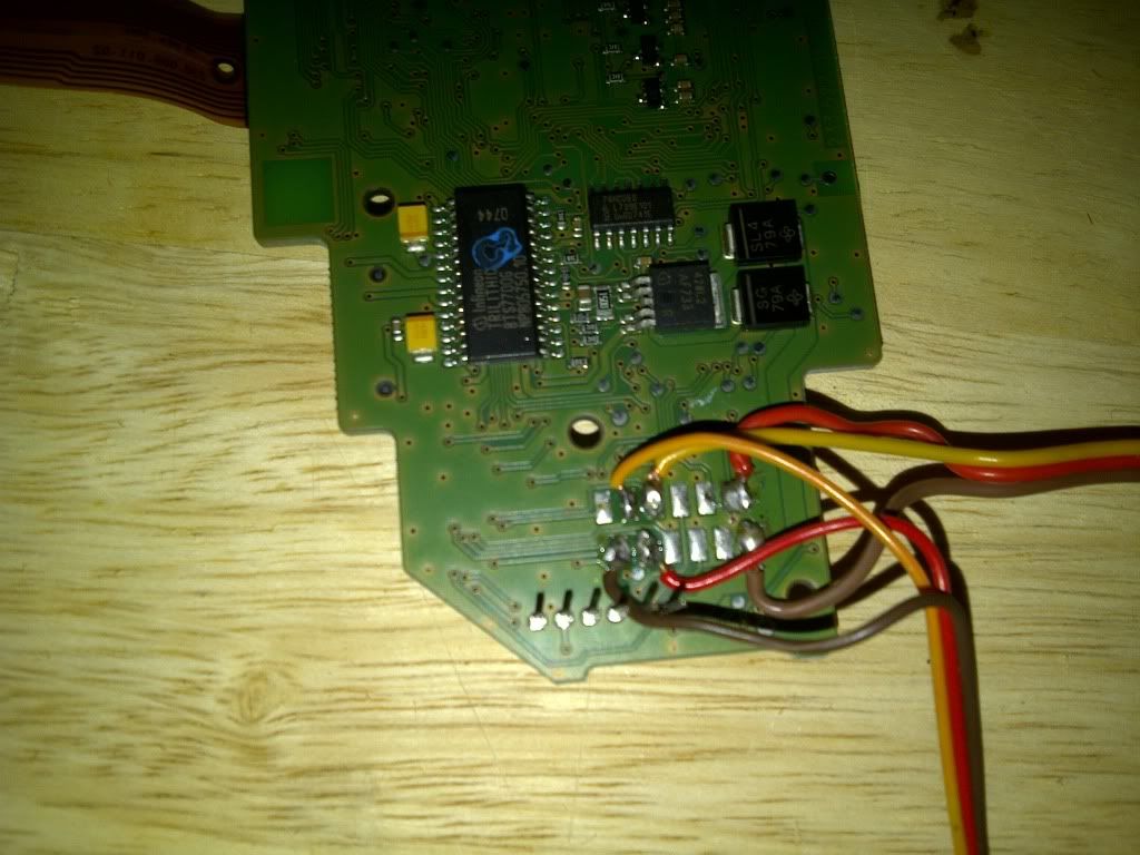
Step 5:
If you guys notice, there's no wiring tapping for the "P" indicator light. This because of there's no appropriate output for "P" indicator light signal on the circuitry board. Hence, I've to tap it manually from the inside of the knob itself, at the +ve channel on "P" light.
Take out the knob cover carefully:
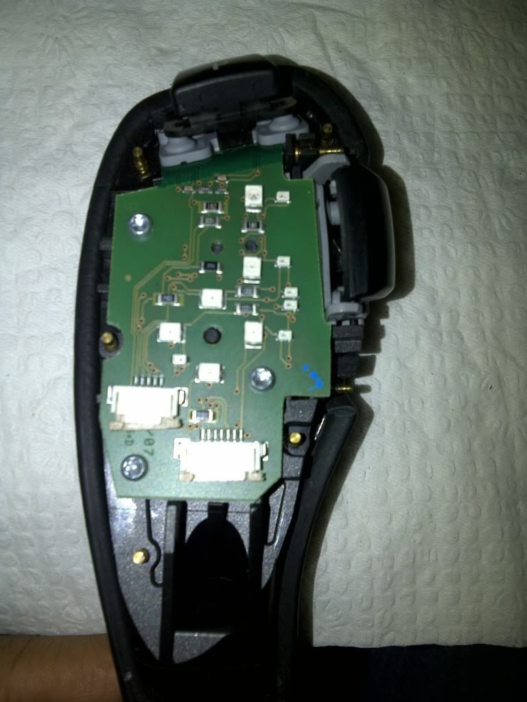
Pull back the logic circuit and u'll find the +ve signal of "P" light indicator. Tap the wire and soldered nicely.
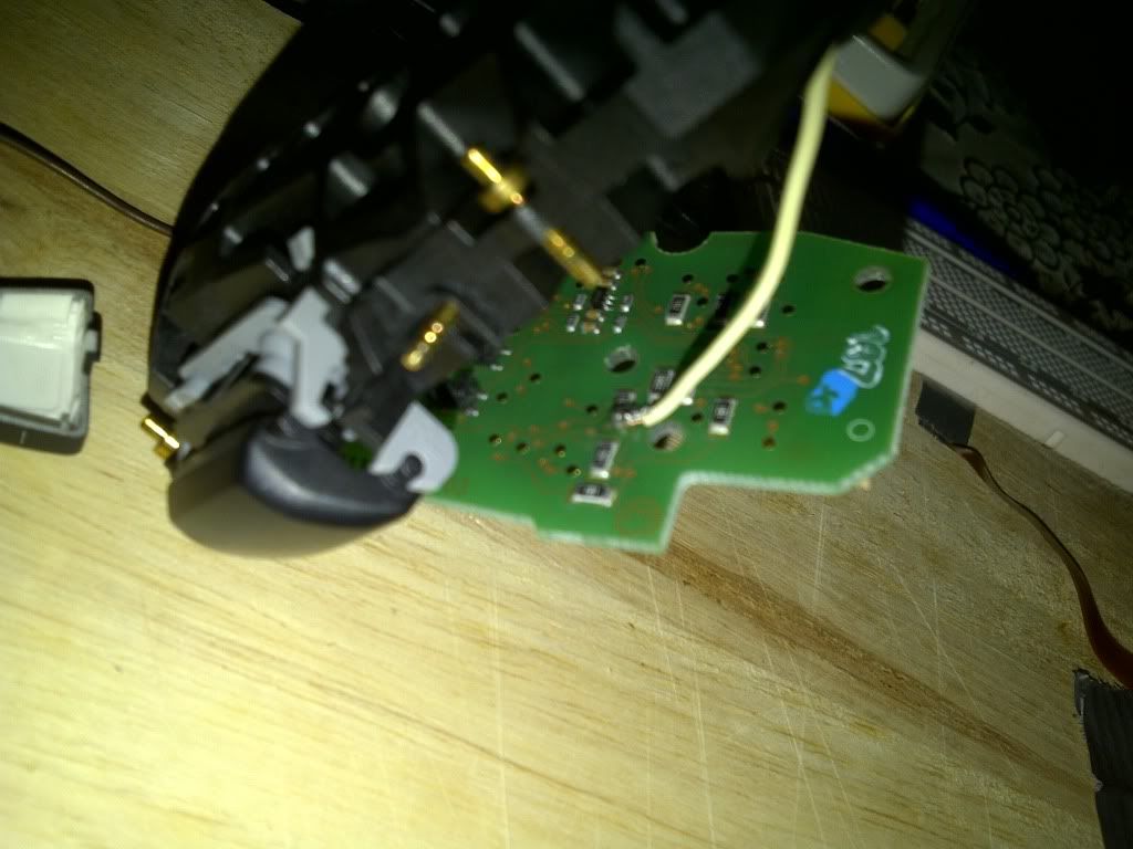
Step 6:
Put the proper label on each connection to avoid any confusion. Try each indicator by using 3Volt batt. All signals indicator must respective to the GND (-ve pole of battery)
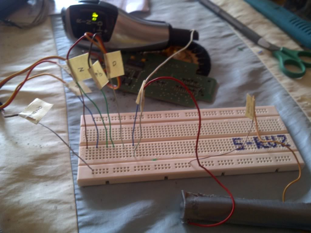
Light functionality test:

Next post:
1) Make up the proper harness onto the OEM gear console
2) Functionality test on the gear console.
To be continue......
Phase: Retrofit LCI E60 Knob into E46 Gear knob (PART 2)
To execute this steps, you'll require:
1) 3mm wires (20cm/8pcs)
2) Multimeter
3) Soldering Iron with lid (high flux)
4) Wire cutter
5) Healthy brain :hmmmm:
Step 3:
Remove the gear faceplate and take out the gear light indicator to find the right signal for the right light indicator (PRND, M/S, GND)

Take out the gear light indicator:
Upside view:

Downside view:

Step 4:
Upon the investigation on the original light indicator and LCI gear knob, I found that the indicator signals should goes as below wiring by tapping the extra soldered harness onto LCI lever's circuitry board.
This is my blueprint of the tapped harness:

Explanation of the blueprint:
The LCI Knob wiring is as follows:
Pin1 (white wire): "R" indicator
Pin2: "N" indicator
Pin3: "D" indicator
Pin4: 0V/Ground for parking/driving light illumination } dim lighting
Pin5: +12V for for parking/driving light illumination }
Pin6: +12V for the brighter "R", "N" and "D/S" indicator
+ve signal @ "P" light: "P" indicator
X1599 is the big white connector:
Pin2: connect to the "P" +ve signal from knob
Pin3: red wire
Pin4: orange wire
Pin5: yellow wire
X1193 is the small white connector
Pin1: grey/red wire
Pin2: brown/black wire (ground)
X1600 is the small maroon/purple connector
Pin1: blue/white wire
Pin2: red/orange wire (goes to Pin#5(with black stripe) @ X1599 & Pin#6 @ gear knob.
X1599, X1193 and X1600 all these connects to the underside of the gearlever faceplate.
How to find the correct pin with the correct output?
This can be done by try and error on each soldered output on the circuitry board by using the multimeter and 3Volt battery, with respective to the GND. I found the GND output is on the most right side of soldered pole (tapped it with brown wire)
Soldering all the harness as below:

Step 5:
If you guys notice, there's no wiring tapping for the "P" indicator light. This because of there's no appropriate output for "P" indicator light signal on the circuitry board. Hence, I've to tap it manually from the inside of the knob itself, at the +ve channel on "P" light.
Take out the knob cover carefully:

Pull back the logic circuit and u'll find the +ve signal of "P" light indicator. Tap the wire and soldered nicely.

Step 6:
Put the proper label on each connection to avoid any confusion. Try each indicator by using 3Volt batt. All signals indicator must respective to the GND (-ve pole of battery)

Light functionality test:

Next post:
1) Make up the proper harness onto the OEM gear console
2) Functionality test on the gear console.
To be continue......
Similar threads
- Replies
- 1K
- Views
- 108K


